sorry Lx is the length along the x axis, so it would be Length
Ly is the length along the y axis, so it would be Width
Lz is the height to the ceiling.
<< responsible for confusion lol
sorry Lx is the length along the x axis, so it would be Length
Ly is the length along the y axis, so it would be Width
Lz is the height to the ceiling.
<< responsible for confusion lol
we were having an argument on width vs breadth, breadth is better as it rhymes with breasts!
I would much rather prefer BREADTH and Li Lj Lk as the i, j, k vector notations like I was saying but … 
(thanks for the monospace tip
corrected it as follows:
Lx, Ly, Lz are room dimensions -
Lx = Length
Ly = Breadth! @FluteCafe
Lz=Height
l, m and n are integers normally within (0 to 4) that help calculate different room modes
l, m and n correspond to axes x, y and z respectively.
For basic case , axial use [l = 1 , m=0, n=0 ] or [ l=0, m=1, n=0 ] or [l =0, m=0,n=1 ]
v is speed of sound 1130 ft/sec , result will be in Hz.
Ok made some gifs lol
added to the o.t.
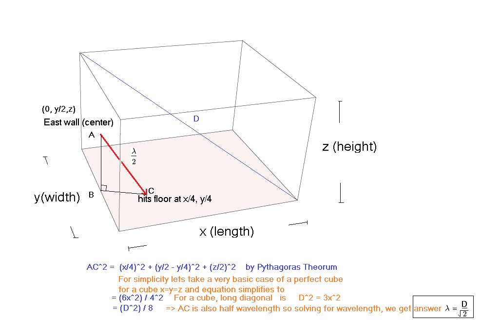
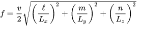
Basic Room modes calculated and explained by simple Geometry.
These can be used to guess the resonant frequencies in a room at a basic level (first harmonic, half wavelength)
wavelength (lambda) is calculated by by studying the geometry of the reflections (this process can be done mentally as well in some cases using handy appoximations)
Axial Modes :
Tangential Mode:
basic tangential modes can be quickly approximated by calculating the diagonal of the room.
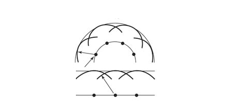
Oblique Room Mode (basic case)
this was a pain in the arse to make… but atleast there is 1 now
Basic oblique modes can be mentally approximated by the inverse root 2 or two thirds approximation method explained below.
Final result:
As modes get complicated, Rayleigh formula can be used as explained in the original topic:
I’m gonna knock the back wall of my control room out and extend it another 12 feet. First I need to get a real good acoustics guy in here to take measurements, and I don’t know that I want to wait 3 months for one to become available. What are some of the questions you would ask an acoustics guy to find out if they know what the fuck they’re talking about before we waste my time and theirs getting them out here just to take measurements and make recommendations for a re-design.
Pictures of the room are in this thread:
I would definitely have them do a real time test (specially since you’ve got a drum set) most would do this, if they avoid it, something smells fishy. Talk about room ratios and what is optimal for you.
Just watch out for how much broadband absorption they recommend to put. Focus more on how they will approach the low ends, closer to your room modes. Hey use the formulas! hehe.
Studio looks great btw! you’ve got brick flooring and partial brick wall that is awesome. You may want to ask them about window treatments if needed, you have glass windows in the back. Not too concerned about mixing room, as you can most likely find a sweet spot if space is a concern.
If you do have the flexibility to give yourself more space, do it just make sure room doesnt become an icecube
aye, when I started the topic I didnt really have a structure or order of things. I grabbed a glass, and a bottle and I started writing. I start off with a topic (resonant boundary distortions) that is much of a less concern in the music industry than the aerospace industry lol. I came off-base and most likely added confusion to many.
What I didn’t realize is that the priorities and order of an acoustic engineer or enthusiast who deals with music is different than one who deals with jet engine cavities. While resonant boundary distortions are less of an issue and also easily handled in the world of music, they are a gargantuan of an issue in jet cavities. We are talking catastrophic damage here.
Anyway, I am going to approach the topic from a different angles, re-prioritize things and adjust the article for both beginners and expert gurus alike. I do intend to write more to it over time. There are many many more things.
Had my east and west flipped in my animated illustration, corrected that
(oblique room mode geometrically explained)
added to the o.t
Sound Pressure, Sound power, Sound Intensity
In acoustics, terms are often changed around; however, they have completely different meanings.
Sound Pressure
When we are referring to sound pressure, we actually mean pressure that is measured in pascals. The pressure of the sound wave itself (usually in air). The pressure of the wave as it hits your ear drums.
In humans, there is a threshold of 20 micro pascals . As in you wont hear a “sound” at a pressure lower than that, however, some other animals still can.
Sound power,
Sound power on the other hand is energy radiated over time. Yes you guessed it correctly, wattage as in the power drawn by the speakers or the source in order to create that sound. Like 10 watt speakers, 1000 watt speakers etc.
Sound intensity is power dispersed over an area. Governed by inverse square law. Sound Intensity drops by a quarter with every double the distance away from the source.
Now that we got that out of the way, how are these entities linked? Is there a common ground, some common terminology we can use?
Short answer, yes there is. It is called DB, Decibels
Long answer, yes and no. In all honesty we are still struggling and arguing to find common ground.
While DB provides a sense of unity to the different aspects of measurements, Decibel itself is a relative unit. As in it requires a reference mode. It is a logarithmic entity that requires comparing one quantity to a reference level of that quantity.
There are different types of Decibel expressions:
In case of Sound Pressure, we call it Sound Pressure Level (DBSPL)
When referring to sound pressure level, we compare pressure of the sound to the minimum pressure required to hear a sound, in case of humans 20 micropascals (Po).
DBSPL = 20 Log (P/Po)
Po = Lowest pressure for ears 20 micro pascals
P = actual pressure
Looking at the logarithmic equation it is easy to see that when pressure doubles, sound pressure level increases by +6 DBSPL as 20 log 2 equals 6
In case of Sound Power we call it DBm
DBm = 10 Log (W/Wo)
W = actual wattage
Wo = reference wattage (normally at 1milliwatt, 600 ohm)
We can see that when power doubles, power level (DBm) increases by +3 DBm
Ham radio operators can most like relate to it. DBm is used more in engineering for impedance matching than acoustics but it is still relevant. However, DBm gives birth to another quantity called DBu or DBV
Analog system operators will relate to this. Power is a square function of voltage, hence we can derive a relationship, providing resistance is constant. In our case lets say 600ohm
Since power is a square function of Voltage, it is safe to say that
DBv = 20 Log (V/Vo)
V= actual voltage
Vo = 1 Volt (or 0.7volt in some cases called as DBu)
Easy to see that when voltage doubles, DBv increases by 6
Analog musical systems rely on DBv or DBu more than DBSPL which is mostly used in engineering.
All that aside, we have also heard the terms RMS, DBFS, DBA and Phon.
RMS, DBFS , DBA and Phon
As digital era descended on us, we needed a new unit that the digital analog converters could relate to.
DBFS is Decibels Full Scale. There is absolutely no mathematical relation between DBFS and DBu
But we do have guidelines, in Europe about 18 DBu is seen as the same as 0 DBFS
In digital realm, 0 DBFS is the maximum level and everything else is negative. (If you notice, other DB units are non negative and their minimum value is 0 with relation to the references)
RMS is another method to measure sound levels, in this case it is root mean square (quadratic mean) of the voltage function in Analog systems over a period of time. Mathematically it is integral calculus, but you get the point.
In electrical engineering terms, a 9V RMS AC supply will lead to the same brightness in a bulb as a
steady 9V DC supply
DBA is pretty much the same as DBSPL but measured with an ‘A filter’. Those not familiar with the A filter, it highlights frequencies between 2000 and 4000 over others, as that is around the resonance modes of our ear canal. DBA is used in design of concert halls and is quite relevant in the field of musical instruments and acoustics.
Phon
Phon relates to psychoacoustics and also in civil engineering. It relates to the DBSPL of a 1khz tone.
In civil engineering, it is used in design of speed deciphering systems or speech isolating systems.
Hope that demystifies some of the issues around terminologies.
There is another DBA called Database Administrator, and their loudness depends on who double dips in the office break room guacamole dip and somehow number of cookies in the jar.
Root mean square that function!
added to the o.t
Now that we understand and know how to calculate room modes, where do we go from here? First step is to plot them all out in a table and look at the data in order from low to high frequencies.
What to do with the Room Mode data
When are are looking at an ordered list of room modes, for simplcitty sake lets deal with axial modes of a 10x10x10 room (ice cube).
we already established that wavelength of a standing wave in a 10ft room is around 56hz, lets say we have an A student who has already calculated the other overtones.
The chart will look like this
It is easy to see that this is a terrible scenario! We have multiple modes at the same frequency and the gap between frequencies is much larger than 20 hz on both sides ( 56 - 112 - 168 ). This means that these frequencies will stand out
quite a bit as there is little to no masking going on.
To a human ear, tones stand out more if there is no tone around 20 hz below and 20 hz above it in frequency. A phenomenon called masking. When tones are within 20 hz apart on both sides, it will be hard to isolate the tones.
Now lets take a look at axial modes of a 10x12x8 room (Lunchbox). Lets assume the same A student has precalculated all of this for us and ordered it as well like a well oiled teacher’s pet.
Frequencies in Hz
We can see that the frequency response of the lunch box is a bit more evenly distributed than the icecube one.
It still has some problems though. We can see that frequencies around 140s are more than 20hz away from their neighbors 112 and 168.
To add to it, frequency 168 is more than 20 away from 141 and 189 and so forth. So even though we dont have all three overlapping modes, we still have an isolation (not enough masking) issue.
There are room sizes where such issues dont exist or are at a minimum like the bonello sizes or the bolt footprint (more on this later), they still dont always rectify all problems.
Truth is even though theory shows some golden (sweet spot) areas, we are not near a defined size rule due to the many variables involved.
Room Sizes, Room Ratios and Room Geometry
(Is bigger better?)
When we talk about a room, lets first ask, what is the room for. For simplicity, lets take a balanced approach. A decent all purpose approach (listening, mixing, tracking, performing)
We know that size of the room affects room modes and different sizes are going to have different room modes.
If it is a fresh build, it is a good idea to look at room sizes first and see what fits the budget, material and architectural
restrictions.
To answer the age old question, is bigger always better?
The short answer is Yes it is, however it comes with strings attached.
In two rooms that are proportional (same ratios) a bigger room will always be better than the smaller room.
Even though bigger rooms have reverberation issues but when compared to strong room modes, room modes win in their villainy.
In that sense, bigger is better but is bigger by a few inches better? not necessarily.
It is too small of a difference to tell them apart.
Room has to be larger enough (capacity differences of around 3 cubic feet and above - more on that another time)
to be able to clearly tell the differences between the two rooms apart.
To a human ear, tones stand out more if there is no tone around 20 hz below and 20 hz above it in frequency.
A phenomenon called masking. When tones are within 20 hz apart on both sides, it will be hard to isolate the tones.
Consider a room much larger than a 10 by 12 by 8 room. Lets say the room is 35 ft by 33 feet by 29 feet.
The room modes will be weaker in the larger room, mind you they will still exist, room modes will always exist in a room any size any shape, even in a spaghetti shaped room.
In a much larger room, room modes will be weaker. Why? because the fundamental axial mode for the 35 feet room mentioned above will be under 20 hz, below the hearing spectrum of the human ear and their overtones, even though will be very much so in the range of 20-250hz, they will be weaker.
Overtones in general are weaker than the fundamental, hence making them less problematic.
Another case for larger rooms is the inverse square law - sound intensity dissipates with distance. Every double the distance, intensity drops to a fourth.
Room Ratios
Now that we have established that going as big as possible with the budget is a feasible thing to do, next thing to consider is what dimensions should they ideally be?
This has been contemplated for about a hundred years and yet we dont have a solid solution. We have some theories that get very close (Bolt, Bonello, Trevor) they still fail in certain scenarios and building conditions.
Many different types of approaches have been considered when deciding on a room ratio for an ideal all purpose audio room. The starting point for all are room modes.
We want to see them more evenly distributed as in no overlapping ones and spread apart within the 20hz sweet range.Earlier statistical approaches were based on averages and standard deviations. They gave us a starting point but a bit more musical approach was needed. Bonello decided to plot them on a scale of third octaves. Which is what gives us the bonello scale. Bolt’s approach and as of many others was statistical. Bonello’s approach does give us sweet spots in the bolt range as well but they deviate after a while. So the bottom line is that there is a zone where Bonello and Bolt meet that is considered a sweet spot.
That size is normally around 9ft by 17ft by 23 ft. A ratio of around 1: 1.8: 2.6
Argentinian Bonello arrived at this by plotting many room modes per third octaves and comparing the response to his main criterions that the curve should be monotonic (always increasing and always decreasing when traced backwards)
He also plotted it against the other 2 conditions we discussed above (20 hz apart on both sides and not overlapping). The result was a curve that satisfied both his criterion and criterion of others.
If you are interested you can plot the room modes of the above mentioned room dimensions and see the curve for yourself. A good excercise for those who are bored!
Even though the apparent ideal size of 9, 17, 23 is still considered by many, there is still a pretty sizable flaw in his analysist. He treated all room modes, axial, tangential and oblique the same.
Tangential and oblique modes are weaker, namely 3DB and 6Db weaker than the axial ones and hence should have lower priorities in real time. He also did not take into account building materials and structural integrity.
A lot of modern approaches start at a baseline of the bonello graph but branch off from there. Many studies are still going on to arrive at a solution that works with building components, materials and prioritization of different modes.
Bottom line however is still the same. Avoid boxes (cubic rooms) and also try to avoid having two same dimensions in the room and try to go as bigger as you can with your budget.
Room shapes
(to splay or not to splay) - Do angled walls matter?
The answer again is Yes and No
They matter to a certain degree as they give more surfaces for sound to bounce off and reduce the intensity, they will still however make room modes. Only this time room modes will be much harder to predict without industrial strength calculus involved! While Rectangular shoebox room modes can be calculated mentally, calculation of irregular rooms will involve a computing strength required to solve a bitcoin puzzle! Since each room is different, having irregular wall only introduces elements of surprises.
Anyway for tracking rooms, they still might be a good idea to have. As in if you already have them, dont bother breaking them down (put down the sledgehammer), just work around it and take advantage of it.
If you dont have them, dont bother adding them as the angles should come from room treatments and not hard walls.
Reverberation and Clear Speech Standards
We may all know that the effect When sound lingers after the source has stopped generating sound is called reverb. Reverb happens when sound reflects of other surfaces and reaches our ears at different times. We have already discussed the resonant effect of reflections (room modes), reverb is yet another side effect of reflections.
Human ear is able to intelligently interpret Phonemes (basic unit of intelligent speech) within 25 to 60 milliseconds. Meaning sounds must be at least 25 milliseconds apart for the ear to see the sounds separately. Anything before that is seen as uni-source and unidirectional (Coming from a single source from a single direction).
Before the 25 millisecond barrier, the precedence effect or Haas Effect is observed - as in if 2 similar sounds arrive within 25 milliseconds of each other, the ear will not be able to tell the sounds apart and the direction of the sound will appear to come from the sound that arrived first, even if the sound that arrived later was relatively much louder than the previous sound. In most cases, this effect is considered a bad thing for speech intelligibility, however this phenomenon can be exploited to create a richer depth in sound mixes where a little intelligibility can be sacrificed for the sake of musical and acoustic nuance (but that is a topic for another discussion).
Coming back to the basics of reverberation and clear speech -
Contrary to phonemes, syllables can take upto 200 milliseconds for the ear and brain to decipher. In theory a clear speech broadcast must be at least 25 milliseconds apart and must not linger past 200 milliseconds. (Hence the Telecommunication Union and European Broadcast standard for 200 ms RT60 reverb time standards for broadcasting control rooms)
The International Telecommunication Union (ITU) standards are often extended to music rooms and mixing rooms. As in most mixing control rooms target to have an RT60 Reverb time of under 200 milliseconds.
RT60 Reverb time is called the time for a sound signal to decay by 60db in a large room after the sound stops. While RT60 is mostly relevant in larger rooms, RT60 standards are still often extended to smaller rooms. In smaller rooms early reflections within 10 to 15db matter more than the overall reverberant field of sound of 60db. Which is why smaller rooms focus more on treatment of early reflections and larger rooms focus more on critical distances and the overall reverberant field.
Lets talk about RT60 a bit more,
Wallace Clement Sabine, a harvard based acoustic engineer of the boston symphony hall established a relationship between the reverb time RT60, the volume of the room and total surface absorption of the room.
Today we deal with absorption in units of Sabin.
Absorption of a surface in Sabins equals the area times the absorption coefficient of the surface.
Each building material has a sound absorption coefficient measured from 0 to 1 Sabins per sq ft in most cases ignoring sound diffraction from edges (another topic of discussion).
For example a solid wooden door has an absorption coefficient of 0.14 at a frequency of 125 Hz.
The formula empirically derived by Sabine is
RT60 = 0.049 x Volume of Room in cubic feet / total absorption of the room in Sabins
Total absorption = sum of Area of each surface multiplied by absorption coefficients.
Octave Bands and Absorption:
In acoustics, we always deal with sounds in "Octave Bands"
31.5, 63hz, 125 hz, 250hz, 500hz, 1kz, 2khz, 4khz, 8khz, 16khz
Each frequency has a different reverberation time, this is due to the fact that each frequency has different wavelengths and different travel times as discussed previously. Ideally (according to broadcast standards) the goal is to achieve similar reverberation times in each frequency band and in a perfect world, around 200ms or 0.2 seconds.
Example:
Lets take an example of a brick and mortar room with a concrete floor with dimensions:
14 ft by 14 feet by 10 feet.
The room has a volume of 1960 cubic feet, hence the total absorption needed for room to have a Target RT60 of 0.2 seconds is 412 Sabins.
Total Absorption needed to achieve the broadcast standard = ( 0.049 * 1960 ) / 0.2 = 480 Sabin
Now Lets calculate how much actual absorption is in the that room:
The absorption coefficient of Brick and Mortar is around 0.1 around 500hz
The absorption coefficient of concrete floor is around 0.05 around 500hz
Total Absorption of Concrete floor = 14x14 * 0.05 = 9.8 Sabin
Total Absorption of The Brick and Mortar Ceiling = 14x14 * 0.1 = 19.6 Sabin
Total Absorption of 4 Brick and Mortar Walls = 4x (14x10) * 0.1 = 56 Sabin
Total Absorption of the room = 9.8 + 19.6 + 56 = 85.4 Sabin
As you can see that we are about 400 Sabin Absorption short of achieving our goal of 0.2 second Reverb time which means we need to find absorptive material to cover for about 400 Sabin of Absorption. This is in addition to dealing with room modes. So ideally you want to find absorptive material closer to your problem room modes while still covering about 400 Sabin worth of absorption in the above mentioned room.
Reverb in small rooms
In smaller rooms we deal with early reflections (within 15 milliseconds to 25 milliseconds) to stop comb filtering we discussed earlier. Please be advised that this is not the same as flutter echo as commonly misunderstood. A flutter echo is separated usually by more than 60 milliseconds, it is a strong delayed reflection between 2 parallel walls. Flutter echoes
tend to go away as we treat smaller rooms for early reflections but the treatment itself does not focus on flutter echoes, it focuses on comb filtering.
Broadcasting Union suggests that a signal should decay by 10db (in some cases 15db) within the first 15 milliseconds for certain frequency ranges.
The mirror trick:
To find early reflection zones, put a mirror on each side of the wall and ceiling and if you see your speakers in the mirrors from your listening position, that will be your point of first reflection and the first to be treated. Absorptive or scattering material is usually required at this location. With absorption we target for sound level to drop by 10 db or more and for scattering the goal is to make the sound travel 17 feet or more before reaching our ears.
Why 17 feet? its simple, divide 17 feet by speed of sound 1130 and you get 15 milliseconds (the broadcast recommendation)
Those are some guidelines at a very high level. Of Course, it depends on the purpose of the room. If you want a room to sound reverby, you can control how much absorption you add so you can get your target reverb times. This is only recommended for tracking instruments and not necessarily for control room mixing. You dont want natural reverb times of the room messing around with the reverbs you added with the plugins tarnishing your sound image. For control rooms, the reverb times should be rather tamed to below 200 milliseconds as recommended by the broadcasting standards.
That’s all for now folks, next up is Sound Diffusion.
Sound Diffusion
The blaring question - Is Diffusion necessary?
There is some debate around diffusion; some say diffusion is a must and some say it is a luxury and not needed in most cases. While there is some ambiguity surrounding the issue and that has to do with confusion between diffusion and scattering, there is no doubt that diffusion is indeed a very effective and proven way to liven up a room without losing accuracy . Diffusion was first effectively demonstrated by a German physicist Manfred R. Schroeder.
Diffusion can be used alongside absorption to treat reflective rooms but without removing too much sound energy; result is a more diffusive and lively room over a drier or dead room. Diffusion allows high frequencies to remain in space longer compared to absorption. If the room is overtreated with absorption, too many high frequencies could get absorbed, resulting in a dead, boomy and dry room. Diffusion can also help minimize flutter echoes in smaller rooms. In theory a room needs a combination of both, diffusion and absorption.
Diffusion Vs Scattering
Difference between Diffusion and Scattering is often under misunderstood. Diffusion and Scattering are remotely related (as in they both involve use of reflective surfaces) but they are also conceptually very different. Diffusion is the process by which sound intensity and sound pressure is eviscerated evenly. In other words diffusion is a controlled capture and re-release of sound energy. Diffusion operates on principles of Phase shift and Boundary interference (we discussed earlier) causing waves in different phases from adjacent point sources to mingle and create a normalized spread of sound pressure over an area. This is also known as Huygen’s principle of diffusion.
The same principle is also used by concert array based PA systems, where speakers are stacked on top of each other or to the side. The Array of speakers is able to control the sound energy released as in, they are able to diffuse sound energy evenly in the concert hall by creating managed phase shifts between speakers.
Scattering, like diffusion also results in a spread of sound energy, however it operates on principles of reflection from hard surfaces as opposed to temporal phase shifting in diffusion. In scattering there is no phase change as sound waves do not change phases after reflection from hard surfaces. Scattering is a result of such reflections from flat angled surfaces and may also include diffractions from edges. While both methods, diffusion and scattering spread energy around, the key difference is that in scattering, sound just bounces off in different directions with similar intensity without any phase changes, as opposed to diffusion where there is an actual redistribution and re-release of sound pressure as a direct result of phase cancellations.
Scattering relies on inverse square law for reflections to diminish over time. Scattering can be unpredictable in many cases, and may also create unpredictable room modes if scattering surfaces are large enough. Diffusion on the other hand has a controlled and predictable response.
So when to use scattering and when to use diffusion?
Scattering in other words can be seen as stronger (shinier) and diffusion can be seen as softer (warmer). While both have their own purposes, some products can do both, scattering and diffusion simultaneously.
Scattering is used in situations where more shine and sparkle are needed on the high ends, for example tracking rooms can benefit greatly from controlled scattering. Diffusion is used where environment needs to be more softer, controlled and predictable, for example mixing control rooms, home theatres and other listening rooms.
Diffusion can be used in both tracking rooms and mixing rooms, however strong scattering solutions are not recommended for mixing rooms.
Basic QRD Diffuser
In the scope of this article, we will discuss a type of diffuser called the Quadratic Residue Diffuser (QRD Diffuser originally developed by Robert Schroeder) also commonly known as a quadratic diffuser.
We have established that diffusion operates on phase changes, so how exactly does a QRD Diffuser do that? Lets find out!
Example:
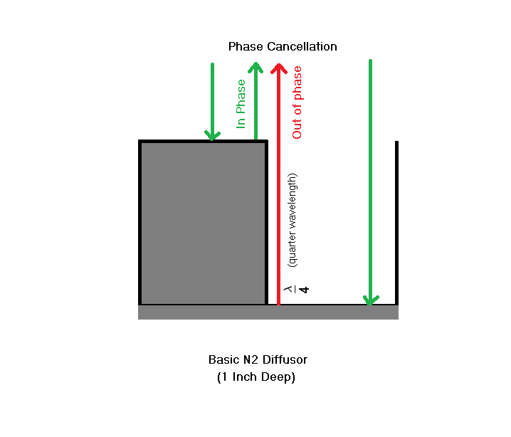
Lets take a foot long solid wooden strip about 2 inch thick and a foot long hollow wooden strip of lets say 1 inch deep, 2 inch thick and glue them next to each other as shown. What you will get is a very basic N2 diffuser pattern.
How big does a diffuser have to be?
Due to size restrictions, diffusers usually target low-mids to mid-high frequency spectrums. To diffuse low frequencies, the diffuser itself would have to be very large as low frequencies have very long wavelengths.
If an obstacle is not around the size of the wavelength of sound at a particular frequency, sound wave would act like as if the obstacle wasn’t there, as in, it would reflect back from the wall ignoring the 3 dimensional geometry of the diffuser. The diffuser has to be at least as large as the wavelength of its lowest target frequency. To target really high frequencies, the geometrical elements on the diffuser would have to be very small, borderline microscopic sizes and narrow region acoustics would take effect. Narrow region acoustics is another big area of discussion. In most cases a diffuser is a few feet wide and a few inches deep.
How does a diffuser work?
Diffuser relies on hollow cavities (wells) to create a phase shift. When sound of certain frequencies enter these wells, they get reflected back with a delay (a temporal phase shift) and when they mix with the signal that is in phase (as the one reflected from the top of the solid strip or from a different depth) it creates a phase cancellation scenario. When these 2 adjacent waves fronts come out of a point source (i.e. a slit like opening), the phase cancellation creates a new pressure distribution (a wider, combined disc like 180 degree spread as speculated by the Huygen’s principle).
Each point source on the previous wavefront (wavelets) becomes source of another wavefront in that direction.The result is that the sound feels evenly dispersed in all directions in the nearby area.
How is phase cancellation a good thing in this case?
The phase cancellation scenario described above resembles the speaker boundary interference condition we discussed earlier. Sound that gets reflected from the back of the speaker and mixes with the main signal of the speaker and whatever frequency has the same wavelength as four times the distance of the speaker from the wall ( quarter wavelength rule ) gets cancelled or phased out. Except in this case it is good thing as it is happening to higher frequencies and not at the listening position. This time it is happening at the walls where diffusion or attenuation is needed. This is a more controlled phase cancellation.
In a diffuser, these wells (cavities) are engineered at specifically quarter wavelength depths, targeting particular frequency ranges.
Quarter Wavelength Significance
You may have heard the term quarter wavelength thrown around during acoustic discussions. What does it really mean and how is quarter wavelength significant here?
Quarter wavelength is important in wave physics as a wave has maximum amplitude at quarter wavelength from its starting position and minimum amplitude (0) at half wavelength. Considering that a wave started at 0 degrees (origin). Quarter wavelength is also the 90 degree (pi by 2) marker on the timeline and Half wavelength is 180 degree (pi) marker.
So what is so important about reflections from the quarter wavelength marker? When a wave reflects back from a quarter wavelength distance, it has travelled exactly 180 degrees (90 degree round trip!), as in it is delayed and temporally out of phase by 180 degrees when compared to the non reflected wave. The comparison is important because the wave itself does not change phase upon reflection compared to itself, but when compared to another non delayed wave, it is 180 degrees out of phase (as in exactly opposite waveforms). When these 2 waves mingle, they are out of phase by 180 degrees causing a complete phase cancellation (a null). While for waves to be completely out of phase is the extreme case scenario that usually defines the lower and upper limits of operations of the diffuser, partial phase cancellation still occurs for other frequencies in the operating range of the diffuser.
Design of a N7 Quadratic Residue Diffuser
Now that we understand the operating principle of a well diffuser, let us find out how we calculate these depths. The depths of the wells of a QRD Diffuser is calculated from a symmetric quadratic function proposed by Schroeder.
![]()
Where x is the position of the well from left to right starting from 0.
N is a prime number
% is the remainder operator (or mod)
The calculation itself is quite basic, divide x square by a prime number and the remainder (hence the name Quadratic Residue) left is the depth, however, the beauty of the function is in the choice of the function itself. Choice of this function by Schroeder makes perfect sense, it gives a scalable and symmetrical pattern on the X axis and it gives results that are very close to the wavelength of frequencies that human ear is sensitive to.
Since we are striving for symmetry here, as in the symmetry of diffusion that leads to a symmetrical dispersion of sound energy, this function is very apt and yet very simple.
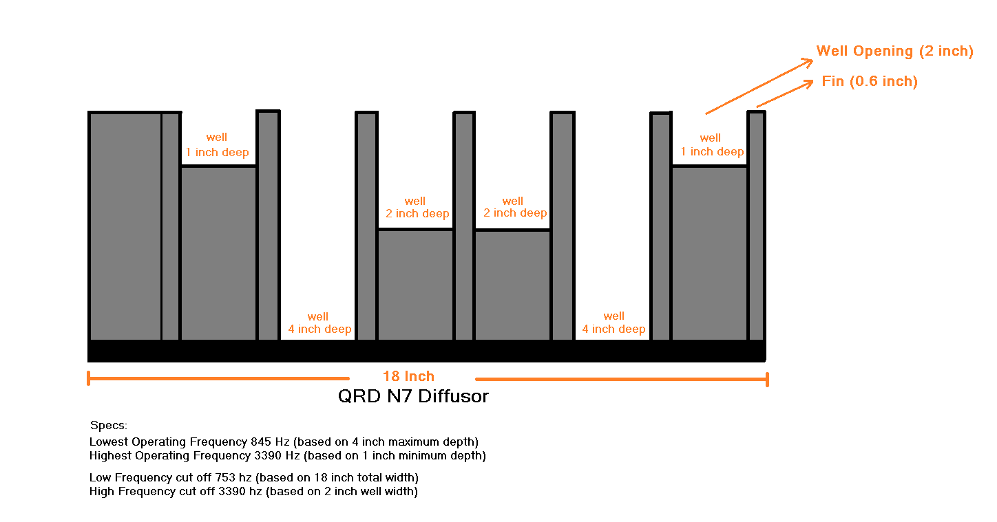
Let us do some basic calculations for a N=7 QRD Diffuser, also called QRD N7
For position Position 0, the remainder is 0
Position 1, the remainder is 1 inch (translates to a 1 inch deep well in fig below)
Position 2, the remainder is 4 (translates to a 4 inch deep well in fig below… etc.)
Position 3, the remainder is 2 (3^2 divided by 7, leaves a remainder of 2)
Position 4, the remainder is 2 (4^2 divided by 7, leaves a remainder of 2 again)
Position 5, the remainder is 4
Position 6, the remainder is 1
Position 7, the remainder is 0
Position 8, the remainder is 1
Position 9, the remainder is 4
…. And so forth
As you can see that the sequence is quite predictable and symmetric,
Let us make a QRD diffuser based on the above pattern (Fig below shows a top cross section of a common QRD N7 diffuser)
The deepest well (in our case 4 inches) dictates the lowest operating frequency that it can diffuse. Applying the quarter wavelength rule, that would mean a wavelength of 16 inches (1.33 ft) total. Dividing the speed of sound by 1.33 we get 845 Hz. Which means that the diffuser will work on frequencies above 845 Hz
The shallowest well (in our case 1 inch) dictates the highest operating frequency that it can diffuse.
Applying the quarter wavelength rule again, we get 3390 Hz.
The total width and height (not shown in cross section above) dictates the low cut off frequency of the diffuser. Since our diffuser is 18” wide by 18” tall, it should be able to catch frequencies that are shorter than the wavelength of 18 inches (1.5 feet). In this case that would be 1130 divided by 1.5, that is 753 hz. It is important that this number is less than or equal to the lowest operating frequency of the diffuser because if the diffuser is not big enough, it might not be able to trap the low operating frequency which would defeat its purpose.
The width of the well in our case 2 inches dictates what is the highest frequency that can get inside the wells and not get absorbed. Usually narrower openings are better but this number is a tricky one because if it is too narrow then narrow region acoustics kick in and signal will get absorbed or attenuated (converted to heat via viscous drag). In that case it will act like an absorber for high frequencies which is not good for a diffuser.
Narrow region acoustics is yet another large area of discussion, specially relevant in jet engine design and other heavy electrical designs. The width of the opening is usually half the wavelength of the highest operating frequency but can be engineered to be narrower with special care for reasons explained above.
If the width of the well is too wide then frequencies will not exhibit Huygen’s phenomenon of diffusion, as wave sources have to be adjacent “point sources (narrow openings or slits)” for the diffuser to work correctly. Too wide and frequencies would just reflect back without much effect.
That is most of the fundamentals of diffusion, the diffusers are designed to be scalable, as in they can be connected extended and used in either dimensions, horizontal or vertical. They can also be connected with other larger more complex diffusers as in N23 QRD Skyline diffuser etc. Overall diffusion is a good solution eliminate some acoustic problems in mixing rooms without absorbing too much sound energy.
Note: I will upload an official blueprint of the QRD N7 later, but feel free to use the images in this article to design your own, it is not very hard. I have constructed several of these myself and they work beautifully.
What are the benefits and drawbacks to the fins in a diffuser?
Also, I’m still a little unclear about the real world benefits of diffusers over scatterers (let’s just assume a curved wall for simplicity’s sake). I get that a diffuser will spread the reflection over time, and a byproduct of that is that it scatters the sound.
But going off the alternative, isn’t diffusion also a byproduct of scattering? You don’t get much of a direct reflection from it (in theory). If I’m scattering the sound when it hits the wall, doesn’t that mean that the sound will be more diffused by the time it gets back to me?
I mean, I get that they are different and that they operate on different principles, but in the real world, is diffusion really that much better? Because it’s way easier, lighter and cheaper to build something that scatters sound rather than something that diffuses sound.
Good questions!
Diffusion works on phase cancellations and Scattering works on straight up reflections from angled surfaces (there is no phase cancellations that happen on the walls in scattering) so there is no “theoretical diffusion” happening as a byproduct of scattering; however, some people use the non-technical definition of “diffusion” as ‘spreading around (dispersion)’ , so in a non-technical way, there is dispersion happening in both cases.
So if both methods spread sound around, why or how do we pick one over another?
I am not going to sell you on one or the other, because both have similar yet very different applications. I will however, explain what effect each of them have on a room and when or why one might need one over the other.
Scattering is usually stronger (higher in energy levels) than diffusion because reflections that happen from hard scattering surfaces are in phase and carry similar energy levels as the incident waves. After spreading them around, it relies just on the inverse square law to diminish the reflections over time, so the high frequencies ring a bit longer compared to diffusion - which has both, phasing and inverse square law working for it. In diffusion, phase cancellations happen right at the walls. Sonically, diffusion creates a “reverse soft-knee” kind of effect where the db levels are brought down gently like a gradient and sound still disperses around evenly (Huygens).
It can also be understood as Scattering is “shinier, sparklier” and diffusion is “softer, warmer”.
Another important factor is that Diffusion is predictable, it has a guaranteed operation on every frequency in its frequency band and the result is also a perfect 180 degree even dispersion regardless of angles of incidences. Diffusers are also very easy to build compared to predictable Scattering solutions that can run up the cost quite a bit. Cheaper diy solutions like popcorn walls and ceilings or random stuff stuck to the walls are a waste of time and aesthetics for a professional mixing control room.
To get scattering to be predictable, requires a lot of engineering work as the surface curvatures and sizes would need to be designed by a computer or some surfaces might not deflect at proper angles, or have an unbalanced dependency on the angles of incidence, surfaces could also have size disparities and might create holes in frequency responses. The worst of all, an improper scattering surface might not have an even, controlled dispersion which is never an issue in diffusion.
Scattering solutions (even poorly designed cheap ones) could be quite beneficial in tracking rooms but a poorly designed or incorrectly done scattering solution can cause problems in mixing rooms. Good scattering solutions are not cheap.
Diffusion is mostly used in mixing rooms for more predictability, but they can be interchanged wherever necessary.
Regarding giant reflective curved walls:
My take on them is, If you already have them, great, dont bother breaking them down. If you don’t have them, don’t bother having them built unless you have an engineer calculate proper curvatures based on your room size. You are better off not randomly building it as it could create gaps in your room modes, only in this case you wont know where (or what frequencies) they are without an exhaustive test. Ideally all curved or splayed surfaces inside a professional mixing room should be treated with proper materials. Exposed glazed concrete or other shiny angled or curved surfaces can create problems.
Fins are required to build the diffuser. They are the planks that are attached vertically to the horizontal board to create the wells (cavities) of the diffuser. Without those planks there would be no diffuser, there would only be a board. The only consideration is that the fin should not be very thick (wide) or the top edge of the fin blade would act like a reflector. It needs to be a thin plank so that the top edge would not reflect the target frequencies for the diffuser.
They are normally 0.6 - 0.7 inch wide (only a wave of 22k hz or higher would reflect off that edge). Goal is to catch the wave in the wells; not scatter them from the top of the fins.
Sorry for a long exhaustive answer, I am not sure if I could have been brief. I had to write it over a period of time (busy days)
Finally wrapped up the full article, you can download a PDF here
Basics of Acoustic Engineering IRD.pdf (497.7 KB)
Finally following up on this.
Most 2d diffuser designs I see have no fins. Some QRD don’t. Is that just because it’s simpler to make without fins?
you may have seen the skyline formation, which is a more complex version of the basic QRD diffuser. A basic QRD diffuser uses larger planks (easier to build). In the skyline formation, the stubs(instead of planks) themselves serve as fins and the cavities are like test tubes instead of longer slits as in the basic variant.
The basic concept of both fins would still be the same . They cant have a cross section too thick (around half inch)
The skyline formation conserves space and the diffusion of sound happens faster. Think of it as dividing the longer cavity of the basic QRD diffuser into smaller patterns of its own
right, I’m just curious about the diffusers that omit the fins altogether. Does that have a negative effect on the diffusion?
If I am understanding your question correctly, you are referring to a “flush surface” diffuser, a diffuser without a fin is just a solid box with cavities. The effect would still be the same on diffusion
The method of construction of a flush surface diffuser is slightly different. A slit is created using a borer saw. Slits of different depths are drilled into a solid wooden box . In the basic QRD diffuser, planks are attached to a board and cavities are filled with wood fillers/saw dust or precisely measured smaller boards.
The end result is still a similar design (adjacent cavities of different depths).
There are certain diffuser variants that use different size slit openings to specifically target certain frequencies. It is easier to do that in the flush surface design method.
The skyline versions dont omit the fins either, they just get replaced by smaller fins (stubs) instead.